Here at Watearth, we take pride in performing several field-based Hydraulic Conductivity Tests to determine design infiltration rates of various soil types for the construction of Low Impact Development (LID) design, including Green Infrastructure (GI).
Field testing is crucial for baseline field parameters, including soil parameters, and establishes a framework for the development of LID. In addition to soil group type, texture, and depth, field testing can be used to ground truth desktop research and confirm actual field conditions, such as conductivity rate and design infiltration rate. The design infiltration rate is ultimately used for portions of geotechnical engineering design.

What is Hydraulic Conductivity and Design Infiltration Rate?
Hydraulic conductivity is defined as the ability of soil to transmit water over a given period. Sometimes the hydraulic conductivity is referred to as the “water infiltration rate” when tested over extended periods of time. The hydraulic conductivity of soil is defined by the ability of the soil to infiltrate water under saturated or nearly saturated conditions over time. The infiltration rate can be provided in various units but is typically provided in inches/hour (in/hr).
Hydraulic conductivity can be affected by a multitude of factors. In soils, texture, particle size, distribution, roughness, shape, and structure each affect the overall hydraulic conductivity, or infiltration rate, of a soil. Soil classifications are often helpful descriptors when discussing hydraulic conductivity and include Hydrologic Soil Groups (A, B, C, and D) and the 12 soil textures (sand, loamy sand, sandy loam, loam, silt loam, silt, sandy clay loam, clay loam, silty clay loam, sandy clay, silty clay, and clay).
The Design Infiltration Rate is ultimately the rate that is used for engineering design and the development of LID. The design infiltration rate is a combination of the equalized infiltrations rates determined by testing, and an incorporated Reduction Factor (RF). RF is determined by weighted criteria and is calculated to afford the design an appropriate margin for error and margin for change of conditions over time; this combination provides a value that represents the long-term performance of the proposed design and construction.

Examples of Field Tests
At Watearth, after years of experience performing field tests for hydraulic conductivity, there are two tests in particular that we have found to be not only efficient but extremely accurate.
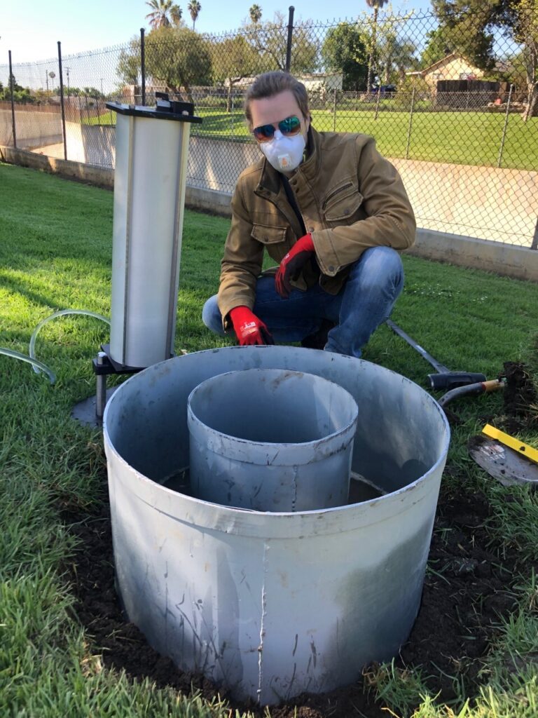
The first test is the Double-Ring Infiltrometer (DRI). Following ASTM D3385 – 18, the tests require driving two rings into the ground where they are filled with water. The outer ring is driven into the ground further than the inner ring, so the inner ring represents only the downward movement of water.
Two Mariotte Tubes, one with 10,000 milliliters (mL) of capacity to fill the outer ring and one with 3,000 mL volumetric capacity to fill the inner ring, are used to fill the rings and maintain a constant head pressure throughout the testing period. The volume of water infiltrated into the rings is then converted to an infiltration rate, using the ASTM calculation methods.
Constant head pressure is a constant reading created by the pressure of water in the graduated column. It can be further described by the Mariotte Tube Principal: “a Mariotte siphon is based on the principle of a Mariotte bottle, which discharges liquid at constant pressure. Moreover, the difference in height between the bottom of the air tube and exit hole of the siphon maintains a constant head in the inner infiltrometer ring” (Bouwer et al.).
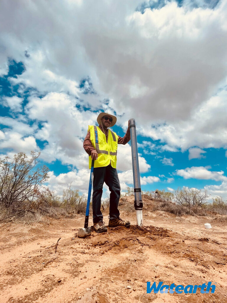
Second, Constant Head Permeameter (CHP) testing utilizes a Guelph Permeameter (GP) to obtain infiltration rates for soils. The GP uses the Mariotte tube principle maintaining a constant head within a borehole, as opposed to the falling head test, which is similar in that soils are tested once saturated, but differs in that the head pressure (the volume of water present at the top) is not required to be maintained . This device consists of a tripod assembly; a support tube and lower air tube fittings; a water reservoir and fittings; and well hydraulic head scale and upper air tube fittings. The GP maintains a constant head as water infiltrates into the soil within the borehole. This rate of infiltration is documented and calculated by the water reservoir volume (Δh) against time (Δt).
Both testing options can be used separately or in combination based upon field scenarios, accessibility, or accuracy techniques.

What is LID?
Low Impact Development (LID) refers to systems and practices that use or mimic natural processes that result in the infiltration, evapotranspiration, or use of stormwater to protect water quality and associated aquatic habitat (EPA, 2021).
At Watearth, we utilize field-based hydraulic conductivity testing to determine the design infiltration rate to design and construct different types of LID to promote preferred hydrologic, water quality, and habitat conditions locally and regionally. Watearth deals in many of the popular LID alternatives: rain gardens, bioretention, biofiltration, permeable pavement, vegetated swales, bioswales, green roofs, trees, vegetation, infiltration basins, green streets, blue roofs, subsurface detention, rain barrels, and cisterns.
Watearth’s work
Watearth takes on numerous jobs that involve DRI and CHP testing for LID design.
We worked with Los Angeles County Public Works (LACPW) on their Adventure Park Regional Stormwater Capture and Integrated Water Resources project. Along with work involving civil design, site assessments, and groundwater monitoring on this project, we created an Operations & Maintenance Plan for Low Impact Development and completed a bioretention LID design featuring native and low water use plans. These designs incorporated DRI.
We have additional work incorporating DRI and CHP testing for LID design for private oil and gas clients and work in a public park.
Contact Watearth today with your project needs.

